
Our mission is to help you realize your idea or concept into a form that truly allows you to progress forward. Whether an electronic enclosure, a new hand tool, or just something you’ve dreamed up and would like to hold in your hand as a prototype, we can help you go from soup-to-nuts in the industrial design process. Designing with all DFx elements in mind throughout, including design for manufacturing, testing, assembly, reliability, repairability and supply chain, we will help you avoid costly, project sinking mistakes that can set back timelines and blow the budget. Then again, maybe you want to avoid all that and just get your idea into your hands, quick and easy? We’re here to help.
In tandem, and if electronics are involved, we can also work with our CM partners (or yours) to arrange for and manage all necessary aspects of electrical engineering, custom PCB board production, gasket manufacturing and supply chain management in the run-up to the mass market.

Early conceptualization usually begins with a pencil and sketch pad. To see where this design went, find some renders in the portfolio.
INDUSTRIAL DESIGN
Your product is composed of its look, durability and level of function. How it is to be used, and by whom (or what), strategically drives its overall design. An early deep-dive on expected user types and use cases is invaluable in the industrial design process.
In some cases, the look of a product hardly matters. Maybe the product will never see the light of day and will be buried in a mud hole, measuring groundwater flow? The look here isn’t so important…but function and durability definitely are. At the other end of the spectrum, the design of a plastic housing meant to reside inside the home may be a bit less durable, yet it will definitely need to look good. Brand impressions!
Our Industrial Design Services include:
Conceptualization
Designing and Engineering with DFx
CAD Modeling
Optimizing
Prototyping / 3D Printing
Animated Product Concept Videos
Testing + Animated UI/UX
Manufacturing Support
Here’s a look at the industrial design life cycle as it moves along the most common, mass-manufacturing path. Perhaps you can see your own project at some step in this process? Well, we’d love to jump in and keep things progressing no matter what stage you might be at.

Some companies approach us having done steps 1-4 (or even 5) and already have a good, proven idea worked out. What’s needed here? Maturation of the concept, strategic component selection, rapid prototyping, forward looking supply chain management and downstream development planning. All of these elements feed into the ultimate development plan that looks well forward to avoid bottlenecks. Done in tandem with your sales and marketing team, a bankable product launch and ongoing distribution timeline can be set.


“Let’s get your idea into your hands.”
Here is one product concept that was designed “fast and loose” to test out user reactions. This model was a cloth-covered device designed for the home. Pictures of the physical version of this device can be seen in the Portfolio. More product and company identity videos can be seen in Product Videos.
9-times Better and Easy to Adopt

When the train was invented, well, it was a no brainer for adoption. Faster, more reliable, able to haul much more…a real game changer. Image Courtesy: Wikipedia.com
In a time where brand loyalty is fueled by convenience more than, well, brand loyalty, any new product entering the market shouldn’t be just marginally better than the competition, but 9 times better. Why? Because people are creatures of habit. And old habits die hard. Unless something is dramatically better and easy to adopt, consumers just won’t extend the effort.
When the train was invented, well, it was a no-brainer for adoption. Faster, more reliable, able to haul much more…a real game-changer. Image Courtesy: Wikipedia.com
Even if life-changing, when consumers must also learn new behaviors to use the product or service, or face things like trying to port over 7,000 emails to a new provider, it will likely be doomed to fail. Here again, consumers are creatures of habit. So, big, real innovation + easy adoption through pre (or mostly known) behaviors = signs of a product concept worth further investigation.
Product development is a multi-step process that benefits firmly from strong market/user research and specific use case definition. As the old adage goes, “the goal should be to build ’pain killers‘ and not ’vitamins.’” To be sure, we don’t really see the benefits of a vitamin, at least not in an instant gratification sense, but the value of a painkiller is immediately felt. Steps in the strategy, discovery, analysis and design sections are important to get the correct user and market fit.
Project Types
Your needs may vary. You may be an individual with an inventive idea that you’d like some light assistance in “making real.” Few things are more satisfying than helping someone realize their dream in a physical, tangible fashion. (As a holder of two patents, I’m all about that -Dan Meyers).
Alternatively, perhaps your company is just starting to ideate a new product concept? We can help in this earliest of stages with market research, product concept brainstorming, and discussions about manufacturing feasibility and best practices. Further on, maybe your company already has a great concept, perhaps even some rough models, and you need help taking the next steps to “make it real.” We can help here too by assisting you with model maturation and adherence to DFx rules as well as working with the right partners on the EE, software, and/or manufacturing fronts. Our long experience with Asurion.com, functioning as their sole, industrial design solution, has prepped us well to help you.
Goals
Our goals are simple:
01.
–
Strategize. Ideas are plenty and often, yet few are true game changers. And let’s face it, consumers are creatures of habit, lazy, sticking with the “tried and true.” So let’s strategize on your product concept, refine it, ensure it is answering a real pain point in a way that is dramatically better than the competition. Let’s build something that consumers get hooked on.
03.
–
Teach. If we can help you understand the steps involved in taking an idea forward, whether its a new widget or an addition on your house, your involvement in our process will leave you empowered. The world of 3D CAD, especially when paired with 3D printing, is very powerful.
02.
–
Design/Prototype. As we get your concept refined, we want to build it. Our goal is to quickly get your hands on 3D visuals, then a physical prototype to create feedback. Then, refine, build again, add components, rinse and repeat. Building fully-functioning prototypes can create very important feedback that guides product direction. Here again, DFx rules the day if ultimate manufacturing is the goal.
04.
–
Satisfy. We are nothing without our clients and customers. Beyond it all, if we don’t make you happy, we lose.

Sometimes fast and loose modeling allows you to get out a shape for quick reaction or function testing. This object above, a toy bug designed at a local grade school where we gave a CAD design lecture, is not prepped for manufacturing but is perfectly useful as one-off and for getting quick reactions. Modeling without DFx is quite a bit faster, but the tradeoff is clear.
Avoid DFx Rules at Your Peril
Companies lose a lot of time and money by designing themselves into a corner as, once they have a functioning prototype and are “ready to take the next step to manufacturing,” they are suddenly told that their hardware is either prohibitively expensive to manufacture or not able to be manufactured at all.
Keeping the list of DFx (Design for Excellence) rules in mind early, which drives design decisions around the manufacturability, assembly, testing, reliability, repairability, safety and supply chain of your product, is key to not getting “boxed in.”
And while there is some real merit to what we term, “fast and loose modeling,” where one builds prototypes quickly and without concern for ultimate manufacturability, some DFx elements should still be considered to avoid complex or impossible features that make associated testing of little value or prohibitively expensive.


Building parts with DFx rules in mind is key to making your work “count” beyond the prototyping phase. The number of different elements that can be “designed for” is vast…and one product may see more weight in certain areas vs. others.
DFx = Design for Excellence
DFx stands for “Design for Excellence.” As a goal, DFx is about the blending of product design and process planning into one common activity. The importance of DFx is underlined by the fact that nearly 70% of manufacturing costs of a product (cost of materials, processing, & assembly) are determined by design decisions, with production decisions (such as machine tool selection or process planning) responsible for just 20%.
As a multi-state acronym, DFx =
DFM - Design for Manufacturing
DFA - Design for Assembly
DFT - Design for Testing
DFR - Design for Reliability
DFRP - Design for Repair
DFSC - Design for Supply Chain
DFS - Design for Safety
And the list of “Design for” elements goes on…
DFM
With Design for Manufacturing in mind, the goal is to design product parts to be most-efficiently manufacturable. Here’s a list of several DFM rules and best practices:
+ Reduce the total number of parts. The reduction of the number of parts in a product is probably the best opportunity for reducing manufacturing costs. Less parts implies less purchases, inventory, handling, processing time, development time, equipment, engineering time, assembly difficulty, service inspection, testing, etc. In general, it reduces the level of intensity of all activities related to the product during its entire life. A part that does not need to have relative motion with respect to other parts, does not have to be made of a different material, or that would make the assembly or service of other parts extremely difficult or impossible, is an excellent target for elimination. Some approaches to part-count reduction are based on the use of one-piece structures and selection of manufacturing processes such as injection molding, extrusion, precision castings, and powder metallurgy, among others.

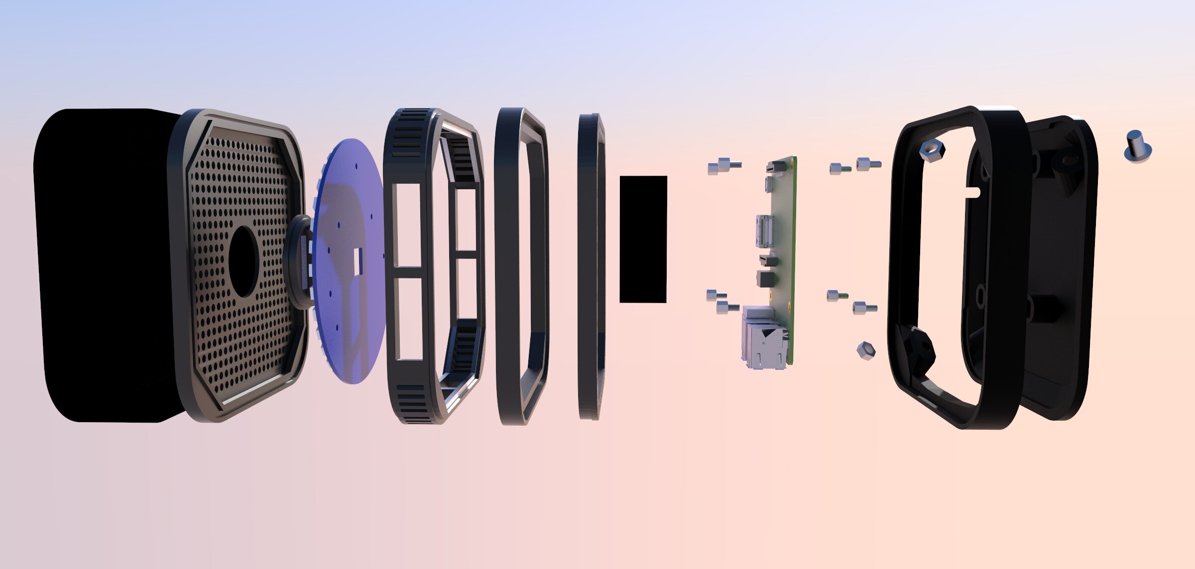
This design is an economical blend between fashion and function. The smooth curves and contrasting textures of this housing are nice to look at and handle, while the interior circuit board is well-enough protected with the necessary components exposed for action using only 2 injection molded parts and two gaskets. Low-cost with a medium to higher value look.
+ Develop a modular design. The use of modules in product design simplifies manufacturing activities such as inspection, testing, assembly, purchasing, redesign, maintenance, service, and so on. One reason is that modules add versatility to product updates in the redesign process, help run tests before the final assembly is put together, and allow the use of standard components to minimize product variations. However, the connection can be a limiting factor when applying this rule.
+ Use of standard components. Standard components are less expensive than custom-made items. The high availability of these components reduces product lead times. Also, their reliability factors are well ascertained. Furthermore, the use of standard components refers the production pressure to the supplier, relieving in part the manufacture’s concern of meeting production schedules.
+ Design parts for multi-use. Design parts to be multi or cross-functional. Some examples are for a part to act as both an electric conductor and as a structural member, or as a heat dissipating element and as a structural member. Besides their principal function, a multi-use part can be designed to have guiding, aligning, and/or self-fixturing features to facilitate assembly, or reflective surfaces to facilitate inspection, etc.

+ Design parts for cross-use. Different products can share parts that have been designed for cross-functional applications. These parts can have the same or different functions when used in different products. In order to do this, it is necessary to identify the parts that are suitable for multi-use. For example, all the parts used in the firm (purchased or made) can be sorted into two groups: the first containing all the parts that are used commonly in all products. Then, part families are created by defining categories of similar parts in each group. The goal is to minimize the number of categories, the variations within the categories, and the number of design features within each variation. The result is a set of standard part families from which multi-use parts are created. After organizing all the parts into part families, the manufacturing processes are standardized for each part family. The production of a specific part belonging to a given part family would follow the manufacturing routing that has been setup for its family, skipping the operations that are not required for it. Furthermore, in design changes to existing products and especially in new product designs, the standard cross-functional components should be used.
Design for ease of fabrication (still DFx here)
Select the optimum combination between the material and fabrication process to minimize the overall manufacturing cost. In general, final operations such as painting, polishing, finish machining, etc. should be avoided. Excessive tolerance, surface-finish requirement, and so on are commonly found problems that result in higher than necessary production cost.
If, for example, injection molding is the end-goal, here is just a small sample of some key items must be kept in mind to avoid downstream issues:
+ Material Determination: Early determination of manufacturing material (ABS, etc.) allows the designer to build features within the confines of the material. Wall thicknesses are an issue of consideration, as are elements of flexibility, heat dissipation, IP (ingress) ratings and more. Knowing your material early-on allows you to design around its boundaries and maximize its usefulness.
+ Consistent wall thicknesses: Proper wall thickness will reduce the risk of cosmetic defects in plastic parts. Walls in any plastic-molded part should be no less than 40 to 60 percent that of adjacent walls, and all should fit within recommended thickness ranges for the selected material.

After the material on the outside has cooled and solidified, the core material starts to cool. Its shrinkage pulls the surface of the main wall inward, causing a sink mark. If the skin is rigid enough, as in engineering resins, deformation of the skin may be replaced by formation of a void in the core. Design Solution: Uniform Wall Thicknesses.
+ Rounded Corners vs. Right Angles: Rounded corners increase part strength and reduce mold wear and tear.

Keep it round! Nature figured this out long ago…we are just following along!
+ Draft Angles Applied: Allows for parts to be pulled from a mold without getting stuck (in the mold) or creating surface scratches. Applying “drafting” as it is referred, is one of the hardest DFM rules to follow early as it slows down the modeling process considerably. Thus, some early, fast-and-loose modeling can occur without the application of draft…just to get shapes out for reaction. That said, drafting should be kept in mind such that no features are created that later cannot be drafted. Coming to an injection molder with a model built all around right angles can be a disaster…making much of the prior work moot.
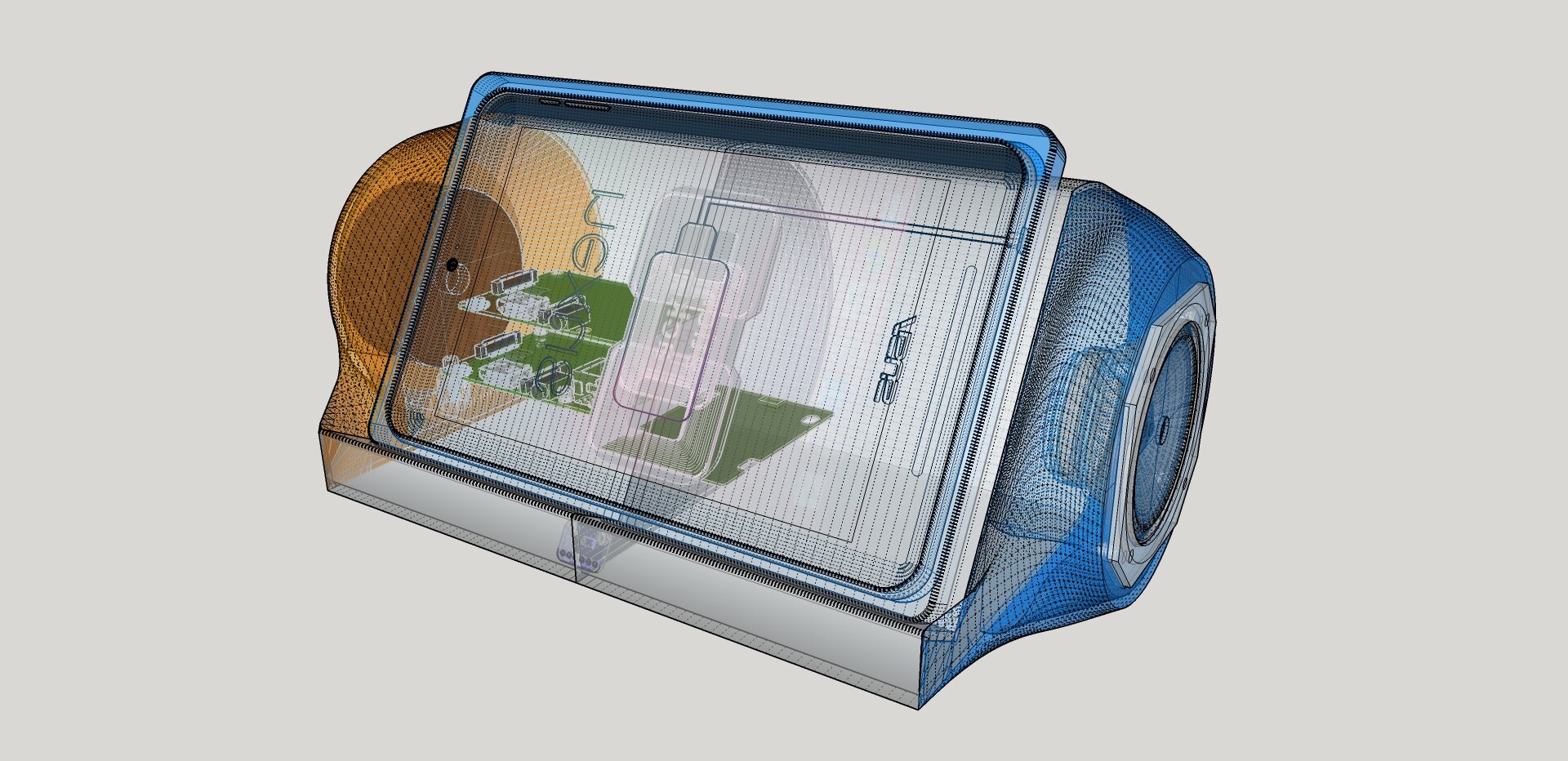
+ Determination of the Parting Line: The parting line is the separation line between two parts. One part can be called the “A” side, and the other the “B” side. The location of the parting line is a big decision that effects the look, function and cost of the entire product. In the below example, the parting line has been optimally located, allowing for protruding components (e.g. 1 GB Ethernet, micro USB and LED light) to exit the enclosure at the parting line. Alternatively, having these “exits” or holes through the case itself would require a “slide action” in the mold shot process. This increases the cost of the mold, the cost per part coming out of the mold (due to increased manufacturing complexity) and reduces the mold’s expected, useful life. Efficient design decisions will look for placing the parting line at the most optimal location, keeping in mind not only the cost to manufacture but also look and function. A balance between all disciplines must be struck.

+ Maximize compliance. Errors can occur during insertion operations due to variations in part dimensions or on the accuracy of the positioning device used. This faulty behavior can cause damage to the part and/or to the equipment. For this reason, it is necessary to include compliance in the part design and in the assembly process. Examples of part built-in compliance features include tapers or chamfers and moderate radius sizes to facilitate insertion, and nonfunctional external elements to help detect hidden features. For the assembly process, selection of a rigid-base part, tactile sensing capabilities, and vision systems are example of compliance. A simple solution is to use high-quality parts with designed-in-compliance, a rigid-base part, and selective compliance in the assembly tool.
+ Minimize handling. Handling consists of positioning, orienting, and fixing a part or component. To facilitate orientation, symmetrical parts should be used when ever possible. If it is not possible, then the asymmetry must be exaggerated to avoid failures. Use external guiding features to help the orientation of a part. The subsequent operations should be designed so that the orientation of the part is maintained. Also, magazines, tube feeders, part strips, and so on, should be used to keep this orientation between operations. Avoid using flexible parts - use slave circuit boards instead. If cables have to be used, then include a dummy connector to plug the cable (robotic assembly) so that it can be located easily. When designing the product, try to minimize the flow of material waste, parts, and so on, in the manufacturing operation; also, take packaging into account, select appropriate and safe packaging for the product.
DFA - Design for Assembly
+ Minimize assembly directions. The fewer steps you have in assembly the lower the cost and the lower the chance for human error. It goes without saying that an assembly process of 4 parts and one, simple QC check vs. 17 parts and 3 QC checks are two, totally different animals. Early consideration of part design, with an aim towards minimization and reduction, will have large implications on the project (positive). Less parts equals less molds as well, thus lowering your NRE (Non-recoverable Engineering Costs).
When setting things up with assembly in mind, all parts should further be assembled from one direction if possible. No doubt, the best way to add parts is from above, in a vertical direction, parallel to the gravitational direction (downward). In this way, the effects of gravity help the assembly process, contrary to having to compensate for its effect when other directions are chosen.
+ Design-in “Fits One-way Only” Elements. To be sure, human error is a leading cause of product failure. This issue is never more prevalent than during the assembly process, particularly if said process is poorly designed. Building in features that make it so a part only fits one, particular way can work to reduce the chance for human error. A good example of this is shown on the below, custom integrated circuit. We built the housing to “key” to the IC, which was built to our client’s spec by one of our CM partners. No matter how you turn the IC, it only fits one way via the asymmetric keys or guides.
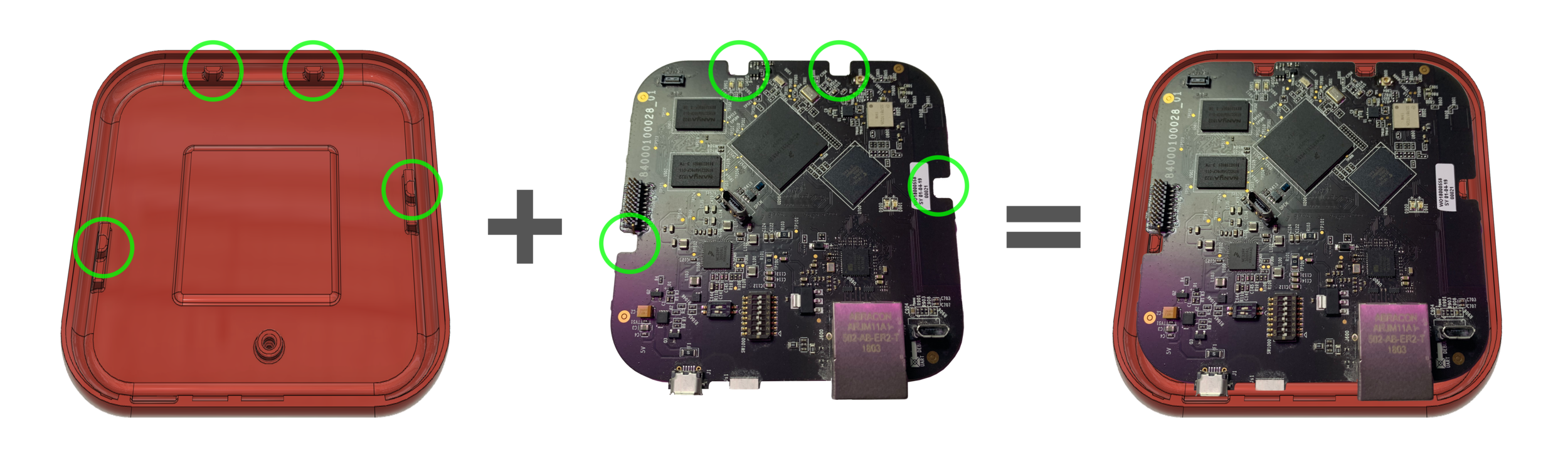
Designing parts to fit together only one way helps to reduce human error and labor time during assembly.
DFT - Design for Testing
Design decisions that affect the testing of certain items throughout the assembly (and post-assembly) processes is crucial. For example, placing all test points on one side of a PCB allows for the tester to quickly perform a validation test (vs. having to physically move to the other side of the product, or move the product itself). Keeping in mind what items need validation to move forward in important to “design in” for efficient assembly procedures and for the reduction of failed states. Easier testing = lower testing costs. Further, if one ignores the need for DFT the product could get far down the development pipeline and suddenly require major re-work due to this ignorance. Up-front and early discussions are needed here to ensure proper testing elements are considered.
DFR - Design for Reliability
Designing your product for reliability is a key goal if you want the product to “last.” Certainly there is a trade-off here as the more reliable or durable a product is, the more expensive it will be (in most cases) to design and build. Nevertheless, a product that needs to stay functional and “go the distance” needs to have elements of strength, elemental protection, ingress blockage, etc. designed in. Failure to address this element early-on is likely cause for expensive re-work.
DFRP - Design for Repair
You don’t see this element of DFx listed very often as DFR is usually referring to Design for Reliability (shown directly above). That said, this design goal is of critical importance if you’re building a product that will need to be repairable. In this case, designing the housing, IC’s, gaskets and other elements for ease of access (for repairs) is important. Forgetting this element until a late stage can truly sink the timeline as suddenly you have a warranty forecast (X% of product returns) and you find out that the cost to make the repair is greater than the cost to replace. No biggie if your product costs just $5. If you’re talking about a $100+ item however, this can kill your business model. Early consideration of DFRP is crucial.
DFSC - Design for Supply Chain
Early design interface and collaboration among designers, buyers, and suppliers incorporating DFx throughout the product development cycle significant improves the ability to impact the design, stay on budget and not have an out-of-stock component push your manufacturing timeline off course. Identifying risks early enables customers to better manage their design, resulting in overall lower project costs and higher VALUE Products.
Ever Heard of GD&T?
While not employed by all engineers, the principal of GD&T, or “General Dimensioning and Tolerancing,” is a critical one. Too often this methodology is ignored and issues of “stacked tolerances” can occur, resulting in improper part and component fits. But let’s take a moment to explain what GD&T is before hawking its critical inclusion. O.K. Think of GD&T like this (in its most basic form): When measuring the width of a part feature, one must pick a point of reference (e.g. the edge of the part). Let’s say said part is 12mm wide. A tolerance must be given to this measurement for the manufacturer to check against, post-molding. Thus, the 12mm spec measurement might be stated as: 12mm +/- .1mm — this means that the part is acceptable if it is anywhere from 11.9mm to 12.1mm wide. Seems simple, and it is. But the problem that can arise is when you go to make the next measurement. If you measure the next part width from, say, the terminus of the prior part width, and here again with some kind of tolerance, then if both part widths are in tolerance, but on the lower or higher side, then these tolerances can “stack” and create the second measurement to actually be outside of tolerance.

This is GD&T explained in its most very basic form. But surely the message is powerful: If the above, stepped shape top was a key tip to fit into an intended slot of 40mm +/- .1mm, well, if we went with the measurements on the left side, we could be in trouble!
GD&T gets much more detailed and covers far more than just basic part measurements. There is an entire library of symbols meant to identify and handle tolerances across every aspect of manufacturing. Here now is an actual part, with GD&T applied in a mechanical drawing. As a review, mechanical drawings are prepared by the designer, for the manufacturer, to be used in the post-manufacturing inspection process. Some elements are redacted in the below image to protect project privacy:

We’d need an entire website dedicated to GD&T to get further into the weeds on this subject. But we’re sure you get the basic idea. Measure all things from a single point of reference for each approach. Side, Side, Bottom. Each point of reference is called a DATUM. Usually there are 2 or 3 datums in any given mechanical drawing.
Read more about GD&T at this excellent resource.
Summary
There are so many different items that go into industrial design. How we attack your project depends, largely, on where you’ve been so far, what research has been done, how “ready” you are to take next steps, and what makes the most sense according to your budget and timeline. Let’s engage to see how we can help!